Pages

Friday, July 15, 2011

Installing Ultra VNC over LAN connection

I had to install Ultra VNC over LAN and WAN and test for all the Windows operating systems such as Windows XP, Windows 2003 Server, Windows Vista, Windows 7 and Windows Server 2008. That was the time I first got my hands on VNC. With outdated documentation, I found it difficult, uninteresting and timewasting. But after putting much effort, I found a great deal about Ultra VNC and other VNC products. With that I was given the task of developing a Remote Desktop application. My knowledge is documented in a series of articles starting from this, with the intention of saving time and energy of anyone who’s reading this.
In this article I’ll explain the task of installing Ultra VNC to work on a Windows 7 machine with screenshots which lacks in many documentations I found for this subject on the internet.

Environment

  • Ultra VNC version: 1.1.9.6
  • Operation System: Windows 8 Ultimate 64-bit

What you need

  1. UltraVNC_1.0.8.2_Setup.exe file (downloaded from UltraVNC home page at www.uvnc.com/download/ )
  2. Active Internet connection (Setup requires to download some files as it installs)

Installation Steps

  1. Execute the exe file.
  2. Select a language.
  3. Accept the ‘License’ document.
  4. Select a destination location.
  5. Select the desired components to install.
  6. Specify a ‘Start Menu’ folder name.
  7. If you are installing on a machine that has Windows Vista or above, you MUST check register as a system service option.

  8. Once all the steps are done finish the installation setup.
There should be 2 machines for the remote desktop concept to make sense. But remote desktop the local machine allow you to verify it’s working. In the remote desktop terminology, server is the machine which we need to remotely monitor or access. On the other hand viewer is the machine from which we remotely monitor the server.
So make sure you install the full setup (only if you are not much familiar with Ultra VNC, otherwise server on targeted machine and viewer on monitoring machine) on both machines and configure them as follows before testing.

Configuring the Ultra VNC Server

  1. Now check your system tray for blue color Ultra VNC logo.
  2. If it’s not there try restarting ‘uvnc service’ or restart your machine.
  3. Right clicking on this icon will give you a menu as below.
  4. Select ‘Properties’ and make sure all options are uncheck.
  5. Now again right click and select ‘Admin Properties’.
  6. In this, in ‘Incoming Connection’ section the displayed 2 ports (i.e Main: 5900 and Http: 5800) can be slightly different depending on your machine’s port availability. The main port number will be required later when connecting to the Ultra VNC server from an Ultra VNC viewer.
  7. Make sure you check ‘Allow Loopback Connections’ in the Incoming Connections section.
  8. Give two different passwords in the ‘Authentication section and remember them, because they will be required when remotely connecting.
  9. In ‘Misc.’ section do tick the first 2 options if you are installing this on a Windows Vista or above OS.
  10. Then apply the settings and press Ok.
  11. After closing the ‘Admin Properties’ reopen it and double check your selections are not changed.
  12. Then restart the ‘uvnc service’ manually.

Configuring the Ultra VNC Viewer

The default setting will be perfectly alright and will not require any configurational changes for the viewer to work.

Initiating Remote Desktop

  1. Start the Ultra VNC viewer.
  2. Specify the VNC Server as <server_ip :: server_main_port> and press ‘Connect’ leaving other options unmodified. It’s wise to first test the VNC installation by remotely connecting to the same machine. That’s why I have connect to localhost in port 5900 which is set in my Ultra VNC server’s ‘Admin Properties’.
  3. If is the Ultra VNC server is runing in the ip that you have provided  and in the port you have mentioned you will see a connection status dialog box and a prompt for server password which you entered in the Ultra VNC server ‘Admin Properties’.
  4. If you want only to remotely view the machine, provide the view only password. If you want to actually work on the remote machine specify the vnc password and log in.
  5. If you have correctly installed and configured the Ultra VNC setup and you are connecting to the local machine from itself you will see something like this, else you will see the correct remote desktop screen of your Ultra VNC server machine.
  6. While a machine is remotely accessed by Ultra VNC, it will not interrupt the logged in user session as in ‘Windows Remote Desktop’. But you can detect that you are been monitored if your machine’s Ultra VNC server icon in the system tray goes yellow from default blue. It’s always yellow if viewers are connected to it.
That’s it for UltraVNC over LAN, hope I saved some of your time with Ultra VNC. Good Luck!

Wednesday, July 13, 2011

Dynamic Column RDLs

When creating reports in RDL there may be cases where you want to represent data in a table, but table column are chosen by the user at the runtime. Assume you have no clue about how many columns will the user choose for the table and what kind of data will it represent.

Normal tables in reports require statically laid columns with statically defined expressions to populate data in them. Matrix comes handy in situations like these. I have explained how to use a matrix to create a table with dynamically populated columns using Business Intelligent Studio that comes with SQL Server Reporting Service (SSRS).

To use this feature database query should result in the following format.

Employee ID (emp_id)

Column Name (col_name)

Column Value (col_value)

1

Name

John

1

Age

25

1

Designation

Software Engineer

2

Name

Smith

2

Age

31

2

Designation

UI Designer

  1. Add a ‘Matrix’ from the toolbox to the canvas
  2. Set the necessary basic elements in the report. Such as Data Source, Data Set, Parameters, etc.
  3. In the newly added matrix insert a ‘Row Group’, and a ‘Column Group’ as follows,
  • Row Group: rows should be group by employee id. In this case ‘col_name’. Hence no 2 employees can have same employee id. If it happens to be, then the initial employee records get overwrite by the second employee who has the same id value.
  • Column Group: columns should be group by column name. In this case ‘col_name’. Hence no 2 columns can have the same name.
  • Cell value should be the data value that satisfies both Column and Row Group conditions. In this case ‘col_value’.

Employee ID <- This is a text box

col_name <- Column Name field

emp_id<- Employee ID field

col_value <- Column Value field

Now when this RDL is deployed and viewed, it will output a table as follows,

Employee ID

Name

Age

Designation

1

John

25

Software Engineer

2

Smith

31

UI Designer

Hence no knowledge is required on number of columns or their content when creating this kind of tables.

SSRS Reports Generation

Creating a New RDL

SQL Server Reporting Service (SSRS) require its reports to be generated in Report Definition Language (RDL). Package also contains a Visual Studio Environment to Develop RDLs, named Business Intelligent Studio.

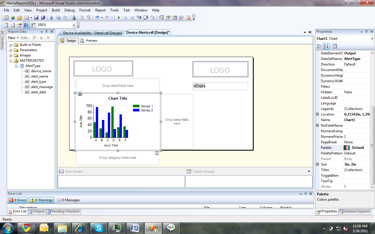
Shown below is a report in Business Intelligent Studio.
Visual area of the report is the canvas. All items on it will be shown in the final published report when viewed. tabular, matrix, charts, labels, images can be drag and dropped to the canvas from the Toolbox (shown vertically on the very left edge in the above image). once the report layout is created you can bind data to it. For any functional report there are few main parts to configure. They are,
  •  Data Source  - which defines the connection string and the credentials to the database.
  • Data Set – which defines the query to execute on the ‘Data Source’ to fetch  data. ‘Fields’ are the returned data attributes for the Data Set.
  • Parameters – these are user inputs that may required by the Data Set queries for the report.
  • Chart, tabular, matrix, label items to be shown in the report.

Adding a New Report Item


  1. Create a new Report Project.
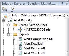
  2. In the solution Explorer do the following changes.
  3. Add a shared data source to access the database.
  4. Right click on ‘Reports’ folder and add a new report Item.
  5. If ‘Report Data’ View is not visible in the workbench, go to ‘View’ menu and select ‘Report Data’.

Setting up Report Data Source and the Data Sets


  1. In the ‘Report Data’ select ‘New -> Data Source’ and point the new data source to the existing shared data source ‘MATRIX24X7DS’.
  2. In the same manner in ‘Report Data’ select ‘New -> Data Set’. In creation the ‘Data Set’ you have to specify the database stored procedure (sp) or the direct query relevant to this dataset. 

Parameters for a Report

Parameters are the only method of getting user input for the report. When adding data set queries the user inputs required for the query to execute are automatically get added under ‘Parameters’ section. we can add new parameters, modify existing ones or even remove them as required.
  1. To add a new Parameter, in the ‘Report Data’ select ‘New –> Parameter’ and follow the wizard.
  2. To modify right click on an existing parameter and choose ‘Properties’
  3. To delete parameter right click and then select ‘Delete’
There are varies methods of taking user inputs using parameters.
  1. If required a date as a input in the wizard select type to be ‘Date’
  2. If you want the user to select from know list of values in the wizard add label-value pairs in the ‘Available Values’ section that will display a dropdown list in the runtime.
  3. If you want to set a default value to a parameter set it in the ‘Default Value’ section of the wizard.
  4. If you don’t want the user to see a parameter mark it as ‘Hidden’ in the wizard.
  5. If the data to available values should be obtain from the database select ‘By Query’ in the ‘Available Values’ section.
  6. If you want the user to provide no input select ‘Allow null’ option.
  7. If you want user to select more than one option from the all available values, select ‘Allow multiple inputs’.
  8. If you want parameters to show available values base on multiple values selected from a previous parameter by the user, set the dependent parameter ‘Available Values’ to previous parameter. set Label to ‘<prev_param>.label’ and Value to ‘<prev_param>.value’

Adding Charts


Column Chart


  1. Add a column chart from the toolbox, select chart type column and hit ‘Ok’.
  2. In chart properties set ‘DataSetName’
  3. Click inside the chart again. Something similar to above image should appear.
  4. Moving mouse over top right corner of all the 3 drop fields will make the selection button appear in blue as for the ‘Drop category field’ in the above image.
  5. In ‘Drop category fields’ click on the selection button and select the data field required for the x-Axis of the chart.
  6. In ‘Drop data fields’ click on the selection button and select the field that was selected for the category field. It will be shown as ‘Count(category_field)’.
  7. Double click on the ‘Chart Title’ and two ‘Axis Titles’, and give the relevant names for them.
  8. Drag and resize the chart as required.
  9. Go to the ‘Solution Explorer’ right click the report and select ‘Build’.

Bar Chart


Creating a bar chart is identical to column chart except the fact that chart type should be ‘Bar’ and hence will not be discuss again.
 

Pie Chart


Creating a pie chart is identical to column chart except the fact that chart type should be ‘Pie’ and hence will not be discuss again.
 

Line Chart


Creating a line chart is identical to column chart except the fact that chart type should be ‘Line’ and hence will not be discuss again.
 

Table


  1. Add a ‘Table’ instead of a chart to the canvas.
  2. Select the table and go to the property window of the table. Set the properties ‘DataSetName’.
  3. Type the column names in the header row.
  4. Select data set fields by clicking the top right corner blue icon and then the required field name in all the columns in the detail row.
  5. Leave the footer row empty or remove. It’s again a static row like the header row.
  6. Set borders, font style and cell background color by right clicking and selecting ‘Properties’ for cells.


Matrix Table


Matrix can be used populate dynamic columns when the creator has no prior knowledge on number of columns. To use this feature database query should result in the following format.
Agent ID Column Name Column Value
A Col_1 Val_1
A Col_2 Val_2
A Col_3 Val_3
B Col_1 Val_4
B Col_2 Val_5
B Col_3 Val_6
  1. Add a ‘Matrix’ from the toolbox to the canvas
  2. Set Matrix’s ‘DataSetName’ in the property plane.
  3. Insert a ‘Row Group’, and a ‘Column Group’ as followed
Agent ID <- This is a text box Col <- Column Name field
Id <- Agent ID field Val <- Column Value field
Now when this RDL is deployed and viewed, it will output a table as follows,
Agent ID Col_1 Col_2 Col_3
A Val_1 Val_2 Val_3
B Val_4 Val_5 Val_6


Multiple Series Charts


  1. Add any chart from the toolbox In the above case it’s a line chart.
  2. Set chart’s ‘DataSetName’ property.
  3. Select a x-axis field from ‘Drop category fields’ top right corner selection button.
  4. Select a group by field from ‘Drop series fields’ same as above.
  5. Select a data field from ‘Drop data fields’ same as above.
  6. Set x-axis title and y-axis title.


Tuesday, July 12, 2011

Microsoft SQL Server Reporting Service (SSRS)

Overview

SQL Server Reporting Service (SSRS) is a server based reporting platform introduced by Microsoft. It’s reliable, comprehensive reporting platform distributed with Microsoft SQL Server since the introduction of ‘SQL Server 2000’ in year 2004.

Same as its competitors such as ‘Crystal Reports’, ‘IBM Cognos’, etc. SSRS also provides attractive features in the areas of data representation, report management and report viewing. SSRS is fully compatible with SQL Server, SharePoint  and uses Visual Studio environment. Yet it can be used with many other commercial and open source DBMSs as mentioned in the features section below.

There are 3 main stages in SSRS report life cycle. They are,

1. Report Creation – Report is defined using the ‘Report Definition Language’ (RDL) which is a XML based markup language. ‘Business Intelligent Studio’ which uses Visual Studio environment can be used to generate reports.

Report

2. Report Deployment – Once the reports are developed they are deployed in a central location in the Reporting Server.

Report5

3. Report Viewing – Once successfully deployed, reports can be viewed through any web connection, expose them through a web service, or publish them directly to a SharePoint site. These published reports can be exported to many formats like PDF, Excel, TIFF, XML or print or even subscribe to by uses. Subscriptions are delivered as Emails or Publish to FTP servers.

7-13-2011 8-43-32 PM

More information regarding SSRS architecture can be found at SSRS home page in MSDN, http://msdn.microsoft.com/en-us/library/ms159106.aspx.

SSRS can be used to produce reports in a business enterprise or can be customized and integrated to custom applications which has a SQL Server based back-end. For whatever the requirement it’s always advantageous to analyze pros and cons of using SSRS to meet your reporting requirement.

Features of SSRS

  • It’s fully compatible with SQL Server Database, SharePoint servers and Visual Studio development environment.
  • Supports relational, multidimensional, XML or custom data sources such as Microsoft SQL Server, OLE DB, Microsoft SQL Analysis Service, Oracle, ODBC, XML, Report Server Model, SAP NetWeaver BI, Hyperion Essbase, TERADATA.
  • Data can be represented in tabular, matrix, charts, images, labels and many other forms.
  • DB logics can be loosely coupled from the business logics that are used to compose the report by calling the Database stored procedures from the RDL.
  • Generated report can be viewed using web and exported to many formats including PDF, Excel, Word, TIFF, HTML, MHTML, CVS, XML, etc.
  • Users can subscribe to reports by configure the SSRS to deliver them in a scheduled time or in intervals as Emails or as FTP file shares.
  • SSRS expose many of its functionalities such as getting report parameters, getting the report output, subscribing to a report, deleting a report, building a report and many more by a Web Service to the outside that can be used to integrate the SSRS features to your custom applications.
  • SSRS provides drill down and parameterized reports.
  • Business Intelligent Studio provides drag and drop features for easy report generations.
  • Anyone with a fair knowledge can develop a custom rendering extension to process the RDL and generate reports.
  • Exported report XMLs can be easily transformed in to any desirable format with the use of a simple XSLT file.
  • SSRS is continuously supported and enhanced by Microsoft since year 2004. Hence has a fairly good documentation support with MSDN.

Weaknesses of SSRS

  • It doesn’t expose all its functions such as drill down facility through its web service. List of all exposes methods can be found at http://msdn.microsoft.com/en-us/library/ms155071.aspx
  • If you are generating and showing reports through SSRS other than directly retrieving raw data from the database it may include additional delays.
  • From SSRS 2005 to 2008 there is slight difference of XML output, and the subscription xml generated by the reporting server that looses direct backward compatibility. Since they are not huge changes, those can be incorporated while development. This will matter only if you use SSRS as the backend of your custom application.

Saturday, December 11, 2010

Resize an image in Java

Given below is a reusable method in Java for image resizing. I’ll walk you through the code explaining what is done by each code line and will give for better understanding. for this method original image name with path and extension should be fed as an argument. Size of a side of the resized image is also required as an argument for this resizeImage method which returns the state of the image resizing action as a boolean.

public boolean resizeImage(String pathAndNameWithExtention, int sizeOfASideAfterResize){
        int size = sizeOfASideAfterResize;
        String name = pathAndNameWithExtention;
        //format name
        String path = "";
        String nameTxt = "";
        String ext = "";
        if(name!=null){
            //get path
            int tempIndex1 = name.lastIndexOf("\\");
            int tempIndex2 = name.lastIndexOf("/");
            if(tempIndex1==-1 && tempIndex2!=-1){
                path = name.substring(0, tempIndex2);
            }else if(tempIndex1!=-1 && tempIndex2==-1){
                path = name.substring(0, tempIndex1);
            }else if(tempIndex1!=-1 && tempIndex2!=-1){
                if(tempIndex1>tempIndex2){
                    path = name.substring(0, tempIndex1);
                }else{
                    path = name.substring(0, tempIndex2);
                }
            }else{
                System.out.println("ERROR! Path Information is wrong.");
                return false;
            }
            //get name
            int tempIndex3 = name.lastIndexOf(".");
            if(tempIndex3!=-1){
                nameTxt = name.substring(path.length(), tempIndex3);
                ext = name.substring(tempIndex3+1);
            }else{
                System.out.println("ERROR! Image name extension is wrong.");
                return false;
            }
        }
        //read original image
        BufferedImage originalImg;
        try {
            originalImg= ImageIO.read(new File(name));
            //get original image width and height
            int width = originalImg.getWidth(null);
            int height = originalImg.getHeight(null);

            //calculate resized width and height to avoid distortion
            if(width>height){
                height = (int)(((float)height/(float)width)*size);
                width = size;
            }else{
                width= (int)(((float)width/(float)height)*size);
                height= size;
            }
            boolean flag = false;
            //create the resized Image
            BufferedImage resizedImg = new BufferedImage(width, height, BufferedImage.TYPE_INT_RGB);
            Graphics g = resizedImg.getGraphics();
            flag = g.drawImage(originalImg, 0, 0, width, height, Color.WHITE, null);
            //save the image
            File outFile = new File(path+"/"+nameTxt+"_resized."+ext);
            ImageIO.write(resizedImg, ext, outFile);
            return flag;
        } catch (Exception e) {
            e.printStackTrace();
            return false;
        }
    }

Majority of the code lines has been devoted to retrieve the image path, name text and the extension of the image name argument of this method. Then the original image is retrieved using the given parameters to a BufferedImage by using ImageIO.read Please note that this image read needs to be handled within a try-catch as given in above complete code.

BufferedImage originalImg= ImageIO.read(new File(name));

Then a small calculation is performed to get the resized image dimensions, by considering the original image width, height and required size of the resized image to avoid distortion. Code segment that follows this calculation is as follows,

if(width>height){
    height = (int)(((float)height/(float)width)*size);
    width = size;
}else{
     width= (int)(((float)width/(float)height)*size);
     height= size;
}

Then the image is redrawn to the calculated width and height as follows by using the Graphic class of Java. Color given in the drawImage method is the background color of the drawn image.

BufferedImage resizedImg = new BufferedImage(width, height, BufferedImage.TYPE_INT_RGB);
Graphics g = resizedImg.getGraphics();
flag = g.drawImage(originalImg, 0, 0, width, height, Color.BLACK, null);

Finally the resized image is written back to the read location with a modified file name as “<name>_resized.<extension>” using ImageIO.write method.

The Java packages that need to be imported for this method to work are as follows,

import java.awt.Color;
import java.awt.Graphics;
import java.awt.image.BufferedImage;
import java.io.File;
import javax.imageio.ImageIO;

To test this method I have created a new class named Test and included the above resizeImage method and the below main method to it.

public static void main(String[] arg){
        Test t = new Test();
        boolean b = t.resizeImage("F:\\testFolder\\TestImage.jpg", 300);
        System.out.println(b);
}

Running this Test class results in creating a new image named TestImage_resized.jpg with max side size of 300px in “F:\testFolder”.

Java Tips

How to Center the JFrame/JDialog in the screen

In the JFrame/JDialog initialize method add the following code lines along with the correct dimensions of your container instead of values 300, 200.

private void initialize() {
        Dimension dim = Toolkit.getDefaultToolkit().getScreenSize();
        int x = (dim.width - 300)/2;
        int y = (dim.height - 200)/2;
        this.setLocation(x, y);
        this.setSize(300, 200);
        ……
}

In the first line it gets the Screen Size to a variable named dim. Please note that the example container’s width is 300px and height is 200px. Using these values we can calculate the x, y positions for the container to appear in the center of the screen. Then the calculated x, y values are fed to the component using setLocation method while dimensions of the container is fed using setSize method inside initialize method of the container.


How to get the working directory in java

It is a quite simple, yet very useful feature provided by Java.

System.getProperty("user.dir");

This will return the current working directory as a string and comes very handy to define relative paths inside Java programs.


How to add an image to a Java container

This can be achieved by adding a new label with the required image’s size, to the container and setting the label’s icon to point the image that is required to be added to the container.

private JPanel getJContentPane() {
        if (jContentPane == null) {
            lbl_Img = new JLabel();
            lbl_Img.setBounds(new Rectangle(101, 9, 164, 16));
            lbl_Img.setIcon(new ImageIcon(System.getProperty("user.dir")+"/icons/edit.png"));
            ……
        }
        ……
}

This code will display  the ‘edit.png’ image in the icons folder of the working directory of the program. Please note that if the image is lager than the label bounds, this will display only the upper left corner of the image to the extent of the defined label bounds. Please refer the “Resize a given image in Java” blog entry to learn how to resize an image in java.

Sunday, October 10, 2010

Java Native Interface

Java Native Interface or JNI is used to define methods in java which will be implemented in C/C++ code. This is very useful to implement some low level functionality which are not supported by Java.
For an example consider that we are creating a java project named “HelloWorldJNI” which has the following structure and location. 
Class Name: HelloWorldJNI
Structure:
HelloWorldJNI
\src
\bin
.settings
.classpath
.project

Package:
test.HelloWorld
Location:
C:\workspace\HelloWorldJNI

Steps in the JNI programming

Step #1: JNI requires the native methods to be declared in java as,
public class HelloWorld{
       public native void displayHelloWorld();
       static{
             System.loadLibrary("HelloWorldDLL");
       }

}
Step #2: compile the class using jdk’s javac compiler as follows,
C:\workspace\HelloWorldJNI>javac.exe src\test\HelloWorld.java
Step #3: Using jdk’s javah.exe create the header file in C/C++ code by invoking following command from the command prompt.
C:\workspace\HelloWorldJNI>javah -jni -o src\test\HelloWorld.h -classpath C:\workspace\HelloWorldJNI\src test.HelloWorldhere “–o” will define the output file name where “–classpath” will define the working path and “test.HelloWorld” will give the input file name.
Step #4: create a Win32 DLL in C/C++ named HelloWorldDLL and copy the DLL file to the C:\workspace\HelloWorldJNI\src location.
Step #5: create a main method in test.TestApp class in java as follows,
public class TestApp{
     public static vois main(String[] arg){
          HelloWorld hd = new HelloWorld();
          hd.displayHelloWorld();
     }
}
Step #6: in the command prompt run the program as
C:\workspace\HelloWorldJNI>java HelloWorldJNI
This entire process is illustrated in the following diagram which was taken from the The JNI Programmer’s Guide. Finally the result will be displayed in the command prompt as “Hello World!” as shown in the below diagram.

A complete JNI learning experience can be gained through going through The Java Native Interface Programmer’s Guide and Specification. Hope this article helped you to do a simple Hello World application correctly which has a packaging structure.


Named Pipes for Inter Process Communication

What is Inter Process Communication (IPC)?

Inter process communication refers to passing of information between processes. These processes can be located either on a single host or on multiple hosts in a network. According to the context in which they operate techniques used for inter process communication should differ to obtain the maximum performance. Given below are some of the popular inter process communication methods.

Different techniques of IPC

Not all operating systems support all IPC techniques. The IPC techniques mentioned below also have different speeds of execution, convenience, reliability levels and security levels. It’s interesting and important to have a good understanding about other alternatives before analyzing one approach of inter process communication in detail. Some of the widely used IPC techniques and the OS support they have are mentioned below,

  • Files:  Supported by all Operating Systems. Very primitive mechanism. Not efficient and highly vulnerable.
  • Message Passing: Used in Java RMI, CORBA, etc. Has lot of limitations.
  • Shared Memory: Supported by all POSIX Systems and Windows Systems. Faster than both Pipes and Sockets.                
  • Sockets: Supported by all Operating Systems. Efficient in server client communication in a network environment.
  • Pipes and Named Pipes: Supported by all POSIX Systems and Windows Systems. Slightly faster than Sockets.

Pipes as an Inter Process Communication Technique

Pipe communication is a effective server/client communication mechanism which enables communication between a server and 1 or more clients. Pipes has 2 forms which has different characteristics. They are,

  1. "Anonymous pipes" (or "Unnamed pipes")
  2. "Named Pipes".

Let’s look at both forms separately. But main focus of this article is to introduce you Named Pipes in detail.

Anonymous Pipes

Anonymous Pipes are used to transfer information between related processes. It should be noted that Anonymous pipes cannot be used to communicate among processes over a network. Unnamed pipes are also unidirectional by nature. Hence to enable bidirectional communication between server and a client, 2 separate pipes need to be created. Normally to satisfy server/client communication between 2 processes, 2 dedicated pipes are created one for reading and one for writing in this scenario. The lifespan of the unnamed pipe is tightly bounds with the lifespan of the process that creates the pipe.

Usage: This is an efficient mechanism to redirect standard inputs or outputs of a child process with its parent process within the same host.

Named Pipes

Named Pipes in the other hand are used to exchange information between related or unrelated processes, within a single host or within multiple hosts over a network. Name of the pipe is assumed to be well known. And any process can access the pipe if it knows the name and has the right privileges. Lifespan of a named pipe is not tightly bound to the lifespan of the process that creates the pipe and hence needed to be explicitly closed at the end of communication. Most important fact about named pipes is that not like anonymous pipes, the same named pipe can act as a server and a client at different occasions. Hence all named pipe peers are equal. 

Named Pipe Example Code

Since pipes behave similar to files, any mechanism used to create or access files can be used for creating or accessing pipes. But we need to keep in mind that the inputs and outputs of a pipe are always byte streams.

There are 4 important methods to implement when using Named pipes for IPC. They are,

  • StartClient
  • ReadPipe
  • WritePipe
  • StopClient

Approach #1 will demonstrate how we can implement a Named Pipe Client which has all these methods and uses 2 separate pipes to establish communication.

public class NamedPipeClient {
    private static InputStream pipeIn;
    private static OutputStream pipeOut;

    public NamedPipeClient() {
           public void StartClient()
    }

    public void StopClient() {
        pipeIn = null;
        pipeOut = null;
    }
    public void StartClient() {
            //initialize the pipe after a small sleep time
            File pipe = new File(“\\\\.\\pipe\\testpipe”);

            try{
                 pipeOut = new FileOutputStream(pipe);
                 pipeIn = new FileInputStream(pipe);
            }catch(FileNotFoundException e){
                 e.printStackTrace();
            }
    }
        public boolean Write(byte[] m_pTxDataBuffer, short totalpktLength) {
        boolean wSuccess = false;
        try {
            pipeOut.write(m_pTxDataBuffer, 0, totalpktLength);
            pipeOut.flush();
            wSuccess = true;
        } catch (NullPointerException e) {
            System.out.println("Exception! Write buffer is null.");
            e.printStackTrace();
        }catch(IndexOutOfBoundsException e){
            System.out.println("Exception! Write length exceeds write buffer size or total packets to write contain a invalid value.");
            e.printStackTrace();
        }catch (IOException e){
            System.out.println("IOException while writing to the pipe.");
            e.printStackTrace();
        }
        return wSuccess;
    }

    public int Read(byte[] pchBuff, int inBufferSize) {
        int byteTransfer = 0;
        byteTransfer = pipeIn.read(pchBuff, 0, inBufferSize);
        } catch (NullPointerException e) {
            System.out.println("Exception! Read buffer is null.");
            e.printStackTrace();
        }catch (IndexOutOfBoundsException e) {
            System.out.println("Exception! Read length exceeds read buffer size.");
            e.printStackTrace();
        }catch (IOException e) {
            System.out.println("IO Exception while reading from the pipe.");
            e.printStackTrace();
        }
        return byteTransfer;
    }
}

Approach #2 will demonstrate how we can implement a simple Named Pipe Client which has all these methods and uses a single bidirectional pipe to establish communication.

public class NamedPipeClient {

    RandomAccessFile rafPipe = null;

    public NamedPipeClient() {
        StartClient();
    }

public void StopClient() {
        try {
            rafPipe.close();
        } catch (IOException e) {
            System.out.println("IOException while closing the pipe streams");
            e.printStackTrace();
        }
        rafPipe = null;
    }

    public void StartClient() {
            //create the pipe
            try {
                rafPipe = new RandomAccessFile( pipeName, "rws");
            } catch (FileNotFoundException e) {
                System.out.println("FileNotFound exception while creating the pipe...");
                e.printStackTrace();
            }
    }
    public boolean write(byte[] m_pTxDataBuffer, short totalpktLength) {
        boolean wSuccess = false;
        try {
            rafPipe.write(m_pTxDataBuffer, 0, totalpktLength);
            wSuccess = true;
        }catch (IOException e){
            System.out.println("IOException while writing to the pipe...");
            e.printStackTrace();
        }
        return wSuccess;
    }

    public int Read(byte[] pchBuff, int inBufferSize) {
        int byteTransfer = 0;
        try {
            byteTransfer = rafPipe.read(pchBuff, 0, inBufferSize);
        }catch (IOException e) {
            System.out.println("IO Exception while reading from the pipe.");
            e.printStackTrace();
        }
        return byteTransfer;
    }
}

Approach #3 will demonstrate how we can improve the Named Pipe Client mentioned in Approach #2 to support non-blocking reads. If explained further, in above example the read function get blocked until at least one byte is read from the pipe. Hence when reading from the pipe is performed continuously from a separate thread, even writes can get blocked when there is nothing to read. For this I have used the length() method available with RandomAccessFile which will provide the pipe data length in a non blocking way. Since StopClient() and StartClient() methods are identical to what is given in Approach #2, I’ll not include them here. In adding to introducing non-blocking read functionality I have introduced locking scheme to prevent deadlocks.

public class NamedPipeClient {

    RandomAccessFile rafPipe = null;
   
static long curLength;
    static boolean writeNotify = false;
    static boolean wrote = false;
    static boolean readNotify = false;

    public boolean write(byte[] m_pTxDataBuffer, short totalpktLength) {
        boolean wSuccess = false;
        if(totalpktLength<0){
            totalpktLength = 0;
        }
        try {
            while(readNotify){}//wait for read to finished
            writeNotify = true;
            rafPipe.write(m_pTxDataBuffer, 0, totalpktLength);
            wrote = true;
        }catch (IOException e){
            System.out.println("IOException while writing to the pipe...");
            e.printStackTrace();
        }finally{
            writeNotify = false;
        }
        return wSuccess;
    }

    public int Read(byte[] pchBuff, int inBufferSize){
        int byteTransfer = -1;
        if(inBufferSize<0){
            inBufferSize = 0;
        }
        try{
            curLength = rafPipe.length();
        }catch(IOException e){
            curLength = -1;
        }
        //handle exceptions
        if(curLength == -1){
            return byteTransfer;
        }
        //handle functionality
        if(!wrote && curLength==0){
            //nothing happened
            return byteTransfer;
        }else if(!wrote && curLength>0){
            //incoming stream. read now
            try{
                while(writeNotify){}//wait for write to finish
                readNotify = true;
                byteTransfer = rafPipe.read(pchBuff, 0, inBufferSize);
            }catch (IOException e) {
                System.out.println("IO Exception while reading from the pipe.");
                e.printStackTrace();
            }finally{
                readNotify = false;
            }
        }else if(wrote && curLength==0){
            //read possible. But not yet available. wait till timeout.
            try {
                Thread.sleep(1000);
            } catch (InterruptedException e) {
                e.printStackTrace();
            }
            return byteTransfer;
        }else if(wrote && curLength>0){
            //input stream available. read now
            try{
                while(writeNotify){}//wait for write to finish
                readNotify = true;
                byteTransfer = rafPipe.read(pchBuff, 0, inBufferSize);
            }catch (IOException e) {
                System.out.println("IO Exception while reading from the pipe.");
                e.printStackTrace();
            }finally{
                wrote = false;
                readNotify = false;
            }
        }else{
            //unknown condition
        }
    return byteTransfer;
    }
}

Hope this article helped you to get a better idea on Named Pipes which will help you in your future work..

Friday, July 16, 2010

Internet Backbone and Route Servers

Autonomous Systems (AS) are large networks usually belongs to different Internet Service Providers (ISP). AS’s are connected to each other through Internet Exchange Points (IX or IXP) which reside at virtual edges of Autonomous Systems. BGP routing protocol, handles the communication among these different AS’s creating the backbone of the internet.

Accordingly at an IXP, many ISPs are connected to each other by external BGP peering. Normally these external BGP connections are done by full mesh method. This creates a scaling problem. Route Server mechanism is one heavily adapted method to resolve this problem. Each ISP's BGP router only peers to Route Server. Route Server serves as BGP information exchange to other BGP routers. By applying this method, numbers of BGP connections is can be reduced [1].

Some of the ISP’s allow restricted public access to their route servers using telnet. Most often they allow the remote users to issue commands such as

  • ping
  • traceroute
  • show ip bgp

without login into the router. These are very useful for taking various measurements of latency, packet failure ratios, etc of the internet. For a list of such route severs with public access capabilities are listed below [2].

Hostname

Location

Provider

IP Address to telnet

AS

Peers

Type

route-server.twtelecom.net

Littleton, CO 80124, US

Time Warner Telecom

66.162.47.58

4323

2059

Cisco 7200 12.1(2)T

route-server.eu.gblx.net

Phoenix, AZ 85044, US

Global Crossing - Europe

67.17.81.187

3549

2035

Cisco

route-server.gblx.net

Phoenix, AZ 85044, US

Global Crossing

67.17.81.28

3549

2035

Cisco

route-server.ip.tiscali.net

Cagliari, 14 -, Italy

Tiscali

213.200.64.94

3257

806

Cisco

route-server.gt.ca

Montreal QC H3E 3B3 Canada

GT Group Telecom

216.18.63.214

6539

295

Cisco

route-server-east.gt.ca

Montreal QC H3E 3B3 Canada

GT Group Telecom

216.18.63.214

6539

295

Cisco

route-server-west.gt.ca

Montreal QC H3E 3B3, Canada

GT Group Telecom

66.59.190.81

6539

295

Cisco

route-views.optus.net.au

Sydney, Australia

Optus Australia

203.202.125.6

7474

293

Cisco

route-views.on.bb.telus.com

Burnaby, BC v5h 3z7, Canada

Telus - Eastern Canada

154.11.63.86

852

179

Cisco

route-views.ab.bb.telus.com

Burnaby, BC v5h 3z7, Canada

Telus - Western Canada

154.11.98.18

852

179

Cisco

route-server.east.allstream.com

Toronto, ON m5v 3g2, Canada

Allstream - East

216.191.14.250

15290

146

Cisco

route-server.west.allstream.com

Toronto, ON m5v 3g2, Canada

Allstream - West

209.82.88.118

15290

146

Cisco

route-server.central.allstream.com

Toronto, ON m5v 3g2, Canada

Allstream - Central

216.191.167.134

15290

146

Cisco

public-route-server.is.co.za

Edenvale, South Africa

Internet Solution

196.4.160.227

3741

85

Cisco

route-server.videotron.net

Montreal, QC H3C4M8, Canada

VIDEOTRON LTEE / QMI

216.113.14.121

5769

59


route-server.eastlink.ca

Bedford, NS, Canada

Eastlink

24.137.100.8

2610:170:ffff::8

11260

21

Cisco

route-server.belwue.de

Stuttgart, Germany

BelWue

193.196.190.135
129.143.103.78

553

20

Cisco

route-server.cerf.net

Alpharetta, GA 30005, US

CERFnet

12.129.193.235

17233

5

Cisco 7200 12.0(22)S2e

For information on router locations and other information visit here.

Some Important Links to Visit

References

[1] “Route Server” Available at: http://www.zebra.org/zebra/Route-Server.html

[2] “Route Servers”, Available at: http://www.lerfjhax.com/route_servers

Tuesday, May 25, 2010

Create Shortcut Specification for IzPack

In IzPack software, operating system specific shortcut specification must be provided along with the common configuration specification to support the shortcuts. This is caused by the OS specific nature of shortcuts’ operation. In other, words today we will discuss how to write the shortcutSpec.xml that is required to accommodate shortcuts in the Windows environment.
Platform: Windows
File Name: shortcutSpec.xml
The root element of this xml document is <shortcuts>.This xml document has 3 other important sub elements under this tag. they are <skipIfNotSupported/>, <programGroup/> and <defaultCurrentUser/>. <skipIfNotSupported/> allows the panel to be silent on a non-supporting system. <defaultCurrentUser/> allows the “current user” to be the default selection for the panel. If this element is not present, the default selection is “all users”. <programGroup/> allows to specify the name of the menu under which shortcuts to be specified.
<skipIfNotSupported/>
<programGroup defaultName="Jefe" location="applications"/>
After these 3 elements, comes the most important functionality providers of the specification. <shortcut> tags each per shortcut, will provides the OS specific details to the installer to create the shortcuts.
Given below is the code for a shortcut to execute a startup.bat of a Tomcat bundle. This will create a desktop shortcut specified by desktop="yes" attribute and a shortcut in the program group specified by programGroup="yes" attribute, under the name Jefe which is defined in <programGroup> tag. In this shortcut configuration data name of the shortcut appears as Jefe – Startup and the required bat file to execute is located in the path given in the target attribute. While name and target attributes are essential to be specified in a short cut, all other attributes are optional. workingDirectory specify the folder in which the startup.bat is located.  iconFile will specify the location and the name of the icon to use for this shortcut, which will appear in both desktop and the program group. description attribute will give a brief description about the shortcut when it is been requested. initialState=”noShow” will hide command prompt opening when bat files are requested to execute. Since I need to monitor the command prompt information at startup of the Tomcat I used the initialState as “normal”. Even though all the attributes expect name and the target are considered optional, programGroup, desktop, startMenu and startup are considered as semi-optional attributes. There value is either yes or no. Any other value other than these two are interpreted as no. createForPack another important child element of shortcut. It will specify under which pack this shortcut is installed. If this pack is not selected while installation, the respective shortcut is omitted automatically.
<shortcut
        name="Jefe - Startup"
        target="$INSTALL_PATH\core\liferay-portal-5.2.3\tomcat-6.0.18\bin\startup.bat"
        commandLine=""
        workingDirectory="$INSTALL_PATH\core\liferay-portal-5.2.3\tomcat-6.0.18\bin"
        description="Jefe Server Startup"
        iconFile="$INSTALL_PATH\images\startup.ico"
        iconIndex="0"
        initialState="normal"
        programGroup="yes"
        desktop="yes"
        applications="no"
        startMenu="no"
        startup="no">

       <createForPack name="core"/>
</shortcut>
Similarly I have created another shortcut to execute the shutdown.bat in the same folder to shutdown the Tomcat server. I’ll not discuss this since it is just a replacement for the word startup by shutdown. Now let’s take a look on how to create a shortcut to execute the uninstall.jar created by the IzPack installer for the Jefe installer.
<shortcut
        name="Jefe - Uninstaller"
        target="$INSTALL_PATH\uninstaller\uninstall.bat"
        commandLine=""
        workingDirectory="$INSTALL_PATH\uninstaller"
        description="Jefe Server will be completely Uninstalled"
        iconFile="$INSTALL_PATH\images\uninstall.ico"
        iconIndex="0"
        initialState="noShow"
        programGroup="yes"
        desktop="no"
        applications="no"
        startMenu="no"
        startup="no">

       <createForPack name="core"/>
</shortcut>
The difference in this shortcut to the one discussed earlier is that we are using a a bat file given below to execute the jar file and has configured following 2 attributes differently to how they were configured previously. initialState=”noShow” and desktop=”no”. The bat file I’m using for this operation is as given bellow,
@Echo Uninstalling…
java –jar uninstall.jar
@Echo Successfully Uninstalled
The full description of the different attributes are given in the IzPack manual under Desktop Shortcuts section. The same shortcuts created for the Unix base system in also given as an example in the IzPack manual under the sub section A simple shortcut specification for Unix under the Section Desktop Shortcuts.

Thursday, May 6, 2010

Installing Ant and Maven

Installing Ant

Installing Ant is very very simple. Following are the steps for that,
Step 1: Download the latest ant binary from http://ant.apache.org/bindownload.cgi
Step 2: Extract it to folder in your machine. In my case C:\ant
Step 3: Set the following environmental variables in your machine
  • JAVA_HOME : path/to/your/jdk (eg: C:\Java)
  • ANT_HOME : path to folder where you extracted your ant copy (eg: C:\ant\apache-ant-1.8.0)
  • PATH : %PATH%;%ANT_HOME%\bin
Step 4: To check whether the installation was successful, in command prompt type “ant” if it displays “build failed” then ant installation is successfully installed to your machine. But if it says it can not identify the command ant then there is a problem in the installation.

Installing Maven 2

Installing Maven is so simple, and is very much similar to the ant installation process. Given below is the maven installation process,
Step 1: Download the latest maven binary from http://maven.apache.org/download.html
Step 2: Extract it to folder in your machine. In my case C:\maven
Step 3: Set the following environmental variables in your machine
  • JAVA_HOME : path/to/your/jdk (eg: C:\Java)
  • M2_HOME : path to folder where you extracted your maven copy (eg: C:\maven\apache-maven-2.2.1)
  • Set the following user variables in your machine (just above the environmental variables). M2 : %M2_HOME%\bin
  • PATH : %PATH%;%JAVA_HOME%\bin;%M2%
Step 4: To check whether the installation was successful, in command prompt type “mvn --version” if it displays the version information then the maven installation is successfully installed in your machine. But if it says it can not identify the command mvn then there is a problem in the installation.